This document is relevant for: Inf1, Inf2, Trn1, Trn2, Trn3
Kubernetes environment setup for Neuron#
Introduction#
Customers that use Kubernetes can conveniently integrate Inf1/Trn1 instances into their workflows. This tutorial will go through deploying the neuron device plugin daemonset and also how to allocate neuron cores or devices to application pods.
Prerequisite
Before setting up Neuron components on your EKS cluster, you must create an EKS cluster and add Neuron-enabled nodes. This section guides you through creating an Amazon Elastic Kubernetes Service (EKS) cluster with AWS Trainium-enabled nodes (Trn1 or Trn2 instances) using CloudFormation templates and the eksctl command-line tool. You’ll configure optimized networking with Elastic Fabric Adapter (EFA) support and pre-configured Neuron components for distributed training and inference workloads.
For detailed information, refer to:
Step 1: Download Node Group Template
Download the node group CloudFormation template for your instance type.
wget https://raw.githubusercontent.com/aws-neuron/aws-neuron-eks-samples/master/dp_bert_hf_pretrain/cfn/eks_trn1_ng_stack.yaml
wget https://raw.githubusercontent.com/aws-neuron/aws-neuron-eks-samples/master/dp_bert_hf_pretrain/cfn/eks_trn2_ng_stack_al2023.yaml
Important template configuration information
Placement Group: Optimizes network speed between nodes
EFA Driver: Installed automatically (ensure
libfabricversion matches between AMI and workload containers)AMI: Uses EKS optimized accelerated AMI with Neuron components pre-installed
Instance Type: Configured for trn1.32xlarge or trn2.48xlarge (update to your desired instance type)
Kubernetes Version: Trn1 templates use Kubernetes 1.25+, Trn2 templates use Kubernetes 1.34+ (update as needed)
Trn2 LNC configuration (Optional):
Trn2 instances use a default Logical NeuronCore Configuration (LNC) of 2. To change it to 1, update the UserData section of the launch template:
--==BOUNDARY==
Content-Type: text/x-shellscript; charset="us-ascii"

#!/bin/bash
set -ex
config_dir=/opt/aws/neuron
config_file=${config_dir}/logical_nc_config
[ -d "$config_dir" ] || mkdir -p "$config_dir"
[ -f "$config_file" ] || touch "$config_file"
if ! grep -q "^NEURON_LOGICAL_NC_CONFIG=1$" "$config_file" 2>/dev/null; then
    printf "NEURON_LOGICAL_NC_CONFIG=1" >> "$config_file"
fi
--==BOUNDARY==--
Step 2: Create Cluster Parameter Script
Create a bash script to capture the parameters needed for the node template:
#!/bin/bash

CLUSTER_NAME=$1
CLUSTER_SG=$(eksctl get cluster $CLUSTER_NAME -o json | jq -r ".[0].ResourcesVpcConfig.ClusterSecurityGroupId")
VPC_ID=$(eksctl get cluster $CLUSTER_NAME -o json | jq -r ".[0].ResourcesVpcConfig.VpcId")

cat <<EOF > cfn_params.json
[
    {
        "ParameterKey": "ClusterName",
        "ParameterValue": "$CLUSTER_NAME"
    },
    {
        "ParameterKey": "ClusterControlPlaneSecurityGroup",
        "ParameterValue": "$CLUSTER_SG"
    },
    {
        "ParameterKey": "VpcId",
        "ParameterValue": "$VPC_ID"
    }
]
EOF
#!/bin/bash

CLUSTER_NAME=$1
CLUSTER_SG=$(eksctl get cluster $CLUSTER_NAME -o json | jq -r ".[0].ResourcesVpcConfig.ClusterSecurityGroupId")
VPC_ID=$(eksctl get cluster $CLUSTER_NAME -o json | jq -r ".[0].ResourcesVpcConfig.VpcId")
CLUSTER_ENDPOINT=$(eksctl get cluster $CLUSTER_NAME -o json | jq -r ".[0].Endpoint")
CLUSTER_SERVICE_CIDR=$(eksctl get cluster $CLUSTER_NAME -o json | jq -r ".[0].KubernetesNetworkConfig.ServiceIpv4Cidr")
CLUSTER_CA=$(eksctl get cluster $CLUSTER_NAME -o json | jq -r ".[0].CertificateAuthority.Data")

cat <<EOF > cfn_params.json
[
    {
        "ParameterKey": "ClusterName",
        "ParameterValue": "$CLUSTER_NAME"
    },
    {
        "ParameterKey": "ClusterControlPlaneSecurityGroup",
        "ParameterValue": "$CLUSTER_SG"
    },
    {
        "ParameterKey": "VpcId",
        "ParameterValue": "$VPC_ID"
    },
    {
        "ParameterKey": "ClusterEndpoint",
        "ParameterValue": "$CLUSTER_ENDPOINT"
    },
    {
        "ParameterKey": "ClusterServiceCidr",
        "ParameterValue": "$CLUSTER_SERVICE_CIDR"
    },
    {
        "ParameterKey": "ClusterCertificateAuthority",
        "ParameterValue": "$CLUSTER_CA"
    }
]
EOF
This script captures the cluster name, security group for control plane connectivity, and VPC ID.
Step 3: Create CloudFormation Stack
Create the CloudFormation stack for the node group.
aws cloudformation create-stack \
    --stack-name eks-trn1-ng-stack \
    --template-body file://eks_trn1_ng_stack.yaml \
    --parameters file://cfn_params.json \
    --capabilities CAPABILITY_IAM
aws cloudformation create-stack \
    --stack-name eks-trn2-ng-stack \
    --template-body file://eks_trn2_ng_stack_al2023.yaml \
    --parameters file://cfn_params.json \
    --capabilities CAPABILITY_IAM
Wait for the stack creation to complete before proceeding. You can monitor the progress in the AWS CloudFormation console.
Step 4: Determine Availability Zones
Identify the availability zones for your cluster:
aws ec2 describe-availability-zones \
    --region $REGION_CODE \
    --query "AvailabilityZones[]" \
    --filters "Name=zone-id,Values=$1" \
    --query "AvailabilityZones[].ZoneName" \
    --output text
Step 5: Generate Node Group Configuration
Create a script named create_ng_yaml.sh to generate the node group YAML configuration. The script requires: region, availability zones, cluster name, and CloudFormation stack name.
#!/bin/bash

REGION_CODE=$1
EKSAZ1=$2
EKSAZ2=$3
CLUSTER_NAME=$4
STACKNAME=$5

LT_ID_TRN1=$(aws cloudformation describe-stacks --stack-name $STACKNAME \
        --query "Stacks[0].Outputs[?OutputKey=='LaunchTemplateIdTrn1'].OutputValue" \
        --output text)

cat <<EOF > trn1_nodegroup.yaml
apiVersion: eksctl.io/v1alpha5
kind: ClusterConfig

metadata:
  name: $CLUSTER_NAME
  region: $REGION_CODE
  version: "1.28"

iam:
  withOIDC: true

availabilityZones: ["$EKSAZ1","$EKSAZ2"]

managedNodeGroups:
  - name: trn1-32xl-ng1
    launchTemplate:
      id: $LT_ID_TRN1
    minSize: 1
    desiredCapacity: 1
    maxSize: 1
    availabilityZones: ["$EKSAZ1"]
    privateNetworking: true
    efaEnabled: true
EOF
#!/bin/bash

REGION_CODE=$1
EKSAZ1=$2
EKSAZ2=$3
CLUSTER_NAME=$4
STACKNAME=$5

LT_ID_TRN2=$(aws cloudformation describe-stacks --stack-name $STACKNAME \
        --query "Stacks[0].Outputs[?OutputKey=='LaunchTemplateIdTrn2'].OutputValue" \
        --output text)

cat <<EOF > trn2_nodegroup.yaml
apiVersion: eksctl.io/v1alpha5
kind: ClusterConfig

metadata:
  name: $CLUSTER_NAME
  region: $REGION_CODE
  version: "1.34"

iam:
  withOIDC: true

availabilityZones: ["$EKSAZ1","$EKSAZ2"]

managedNodeGroups:
  - name: trn2-48xl-ng1
    launchTemplate:
      id: $LT_ID_TRN2
    minSize: 1
    desiredCapacity: 1
    maxSize: 1
    availabilityZones: ["$EKSAZ1"]
    privateNetworking: true
    efaEnabled: true
EOF
Run the script to generate the configuration file. Update the Kubernetes version as needed for your environment.
Example output:
apiVersion: eksctl.io/v1alpha5
kind: ClusterConfig

metadata:
  name: nemo2
  region: us-west-2
  version: "1.28"

iam:
  withOIDC: true

availabilityZones: ["us-west-2d","us-west-2c"]

managedNodeGroups:
  - name: trn1-32xl-ng1
    launchTemplate:
      id: lt-093c222b35ea89009
    minSize: 1
    desiredCapacity: 1
    maxSize: 1
    availabilityZones: ["us-west-2d"]
    privateNetworking: true
    efaEnabled: true
apiVersion: eksctl.io/v1alpha5
kind: ClusterConfig

metadata:
  name: nemo2
  region: us-west-2
  version: "1.34"

iam:
  withOIDC: true

availabilityZones: ["us-west-2d","us-west-2c"]

managedNodeGroups:
  - name: trn2-48xl-ng1
    launchTemplate:
      id: lt-093c222b35ea89010
    minSize: 1
    desiredCapacity: 1
    maxSize: 1
    availabilityZones: ["us-west-2d"]
    privateNetworking: true
    efaEnabled: true
Step 6: Create Node Group
Create the node group using the generated configuration.
eksctl create nodegroup -f trn1_nodegroup.yaml
eksctl create nodegroup -f trn2_nodegroup.yaml
Wait for the nodes to reach the Ready state. Verify using:
kubectl get nodes
Step 7: Install EFA Device Plugin (Optional)
If you plan to run distributed training or inference jobs, install the EFA device plugin following the instructions at the EFA device plugin repository.
Deploy Neuron Device Plugin
The Neuron Device Plugin is a Kubernetes device plugin that exposes Neuron hardware resources to the cluster’s scheduler. It discovers available Neuron devices on each node, advertises them as allocatable resources, and manages their lifecycle. When Pods request Neuron resources, the device plugin handles the allocation and ensures exclusive access to the assigned devices. This integration enables Kubernetes to treat Neuron accelerators as first-class schedulable resources, similar to GPUs or other specialized hardware.
The device plugin registers two resource types with Kubernetes:
aws.amazon.com/neuroncore- Used for allocating individual Neuron cores to containersaws.amazon.com/neuron- Used for allocating entire Neuron devices to containers (all cores belonging to the device)
Deploy Neuron Device Plugin
Prerequisites
Ensure that all prerequisites are satisfied before proceeding.
Installation
Apply the Neuron Device Plugin as a DaemonSet on the cluster:
helm upgrade --install neuron-helm-chart oci://public.ecr.aws/neuron/neuron-helm-chart \
    --set "npd.enabled=false"
Verify Installation
Verify that the Neuron Device Plugin is running:
kubectl get ds neuron-device-plugin -n kube-system
Expected output (example with 2 nodes in cluster):
NAME                   DESIRED   CURRENT   READY   UP-TO-DATE   AVAILABLE   NODE SELECTOR   AGE
neuron-device-plugin   2         2         2       2            2           <none>          18h
Verify Allocatable Resources
Verify that nodes have allocatable Neuron cores:
kubectl get nodes "-o=custom-columns=NAME:.metadata.name,NeuronCore:.status.allocatable.aws\.amazon\.com/neuroncore"
Expected output:
NAME                                          NeuronCore
ip-192-168-65-41.us-west-2.compute.internal   32
ip-192-168-87-81.us-west-2.compute.internal   32
Verify that nodes have allocatable Neuron devices:
kubectl get nodes "-o=custom-columns=NAME:.metadata.name,NeuronDevice:.status.allocatable.aws\.amazon\.com/neuron"
Expected output:
NAME                                          NeuronDevice
ip-192-168-65-41.us-west-2.compute.internal   16
ip-192-168-87-81.us-west-2.compute.internal   16
Deploy Neuron Scheduler Extension
The Neuron Scheduler Extension is a Kubernetes scheduler plugin that provides intelligent, topology-aware scheduling for Neuron workloads. While the device plugin handles basic resource allocation, the scheduler extension optimizes Pod placement by considering Neuron core topology, NeuronCore-to-NeuronCore connectivity, and workload requirements. It ensures efficient utilization of Neuron devices by placing Pods on nodes where the requested Neuron cores are optimally configured. This component is optional and primarily beneficial for workloads that require specific subsets of Neuron devices or cores rather than consuming all available resources on a node.
The scheduler extension is required for scheduling Pods that request more than one Neuron core or device resource. It finds sets of directly connected devices with minimal communication latency when scheduling containers, ensuring optimal performance for multi-device workloads.
For a graphical depiction of how the Neuron Scheduler Extension works, see Neuron Scheduler Extension Flow Diagram.
Device Allocation by Instance Type
The Neuron Scheduler Extension applies topology-aware scheduling rules based on instance type to ensure consistent and high performance regardless of which cores and devices are assigned to containers.
Inf1 and Inf2 Instances (Ring Topology)
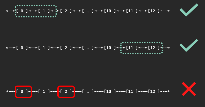
Devices are connected through a ring topology with no restrictions on the number of devices requested (as long as it is fewer than the total devices on a node). When N devices are requested, the scheduler finds a node where N contiguous devices are available to minimize communication latency. It will never allocate non-contiguous devices to the same container.
For example, when a container requests 3 Neuron devices, the scheduler might assign devices 0, 1, 2 if available, but never devices 0, 2, 4 because those devices are not directly connected.
The figure below shows examples of device sets on an Inf2.48xlarge node that could be assigned to a container requesting 2 devices:
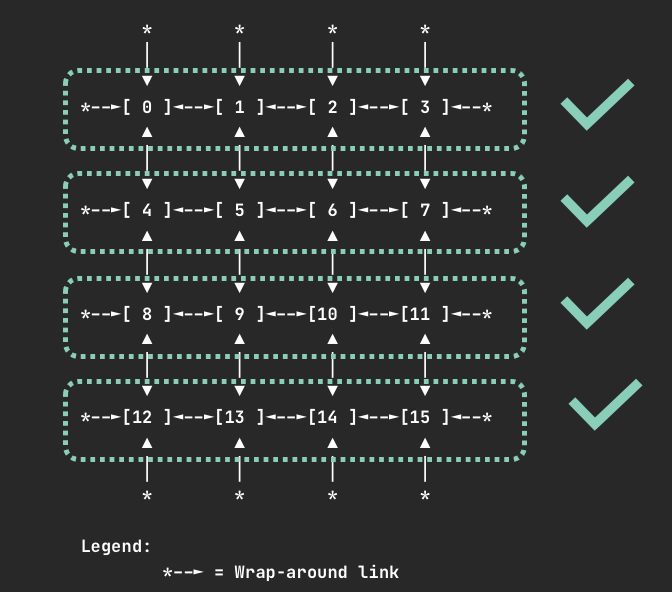
Trn1.32xlarge and Trn1n.32xlarge Instances (2D Torus Topology)
Devices are connected via a 2D torus topology. The scheduler enforces that containers request 1, 4, 8, or all 16 devices. If your container requires a different number of devices (such as 2 or 5), we recommend using an Inf2 instance instead to benefit from more flexible topology support.
If you request an invalid number of devices (such as 7), your Pod will not be scheduled and you will receive a warning:
Instance type trn1.32xlarge does not support requests for device: 7. Please request a different number of devices.
When requesting 4 devices, your container will be allocated one of the following device sets if available:
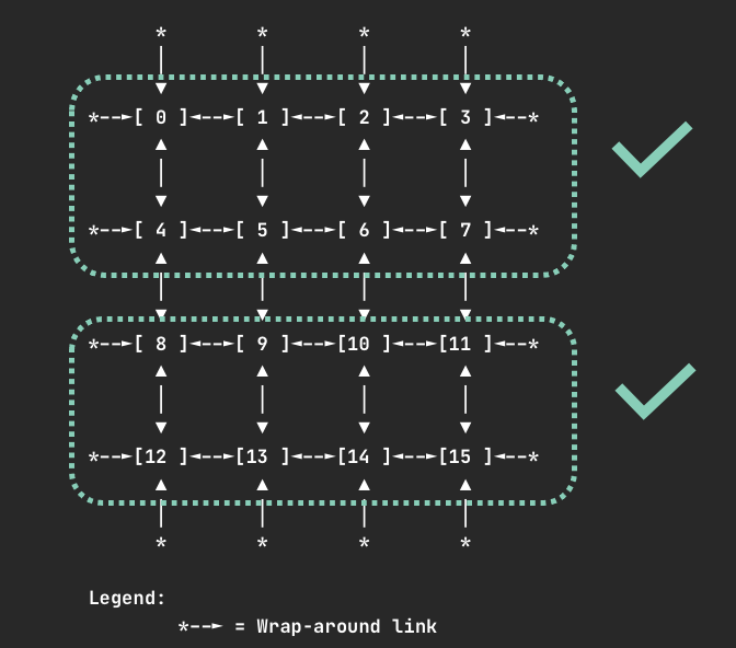
When requesting 8 devices, your container will be allocated one of the following device sets if available:
Note
For all instance types, requesting one or all Neuron cores or devices is always valid.
Deploy Neuron Scheduler Extension
This approach deploys a separate scheduler alongside the default Kubernetes scheduler. This is useful in environments where you don’t have access to modify the default scheduler configuration, such as Amazon EKS.
In this setup, a new scheduler (my-scheduler) is deployed with the Neuron Scheduler Extension integrated. Pods that need to run Neuron workloads specify this custom scheduler in their configuration.
Note
Amazon EKS does not natively support modifying the default scheduler, so this multiple scheduler approach is required for EKS environments.
Prerequisites
Ensure that the Neuron Device Plugin is running.
Step 1: Install Neuron Scheduler Extension
Install the Neuron Scheduler Extension as a custom scheduler:
helm upgrade --install neuron-helm-chart oci://public.ecr.aws/neuron/neuron-helm-chart \
    --set "scheduler.enabled=true" \
    --set "npd.enabled=false"
Step 2: Verify Installation
Check that there are no errors in the my-scheduler pod logs and that the k8s-neuron-scheduler pod is bound to a node:
kubectl logs -n kube-system my-scheduler-79bd4cb788-hq2sq
Expected output:
I1012 15:30:21.629611 1 scheduler.go:604] "Successfully bound pod to node" pod="kube-system/k8s-neuron-scheduler-5d9d9d7988-xcpqm" node="ip-192-168-2-25.ec2.internal" evaluatedNodes=1 feasibleNodes=1
Step 3: Configure Pods to Use Custom Scheduler
When creating Pods that need to use the Neuron Scheduler Extension, specify my-scheduler as the scheduler name. Here’s a sample Pod specification:
apiVersion: v1
kind: Pod
metadata:
  name: <POD_NAME>
spec:
  restartPolicy: Never
  schedulerName: my-scheduler
  containers:
    - name: <POD_NAME>
      command: ["<COMMAND>"]
      image: <IMAGE_NAME>
      resources:
        limits:
          cpu: "4"
          memory: 4Gi
          aws.amazon.com/neuroncore: 9
        requests:
          cpu: "1"
          memory: 1Gi
Step 4: Verify Scheduling
After running a Neuron workload Pod, verify that the Neuron Scheduler successfully processed the filter and bind requests:
kubectl logs -n kube-system k8s-neuron-scheduler-5d9d9d7988-xcpqm
Expected output for filter request:
2022/10/12 15:41:16 POD nrt-test-5038 fits in Node:ip-192-168-2-25.ec2.internal
2022/10/12 15:41:16 Filtered nodes: [ip-192-168-2-25.ec2.internal]
2022/10/12 15:41:16 Failed nodes: map[]
2022/10/12 15:41:16 Finished Processing Filter Request...
Expected output for bind request:
2022/10/12 15:41:16 Executing Bind Request!
2022/10/12 15:41:16 Determine if the pod %v is NeuronDevice podnrt-test-5038
2022/10/12 15:41:16 Updating POD Annotation with alloc devices!
2022/10/12 15:41:16 Return aws.amazon.com/neuroncore
2022/10/12 15:41:16 neuronDevUsageMap for resource:aws.amazon.com/neuroncore in node: ip-192-168-2-25.ec2.internal is [false false false false false false false false false false false false false false false false]
2022/10/12 15:41:16 Allocated ids for POD nrt-test-5038 are: 0,1,2,3,4,5,6,7,8
2022/10/12 15:41:16 Try to bind pod nrt-test-5038 in default namespace to node ip-192-168-2-25.ec2.internal with &Binding{ObjectMeta:{nrt-test-5038    8da590b1-30bc-4335-b7e7-fe574f4f5538  0 0001-01-01 00:00:00 +0000 UTC <nil> <nil> map[] map[] [] []  []},Target:ObjectReference{Kind:Node,Namespace:,Name:ip-192-168-2-25.ec2.internal,UID:,APIVersion:,ResourceVersion:,FieldPath:,},}
2022/10/12 15:41:16 Updating the DevUsageMap since the bind is successful!
2022/10/12 15:41:16 Return aws.amazon.com/neuroncore
2022/10/12 15:41:16 neuronDevUsageMap for resource:aws.amazon.com/neuroncore in node: ip-192-168-2-25.ec2.internal is [false false false false false false false false false false false false false false false false]
2022/10/12 15:41:16 neuronDevUsageMap for resource:aws.amazon.com/neurondevice in node: ip-192-168-2-25.ec2.internal is [false false false false]
2022/10/12 15:41:16 Allocated devices list 0,1,2,3,4,5,6,7,8 for resource aws.amazon.com/neuroncore
2022/10/12 15:41:16 Allocated devices list [0] for other resource aws.amazon.com/neurondevice
2022/10/12 15:41:16 Allocated devices list [0] for other resource aws.amazon.com/neurondevice
2022/10/12 15:41:16 Allocated devices list [0] for other resource aws.amazon.com/neurondevice
2022/10/12 15:41:16 Allocated devices list [0] for other resource aws.amazon.com/neurondevice
2022/10/12 15:41:16 Allocated devices list [1] for other resource aws.amazon.com/neurondevice
2022/10/12 15:41:16 Allocated devices list [1] for other resource aws.amazon.com/neurondevice
2022/10/12 15:41:16 Allocated devices list [1] for other resource aws.amazon.com/neurondevice
2022/10/12 15:41:16 Allocated devices list [1] for other resource aws.amazon.com/neurondevice
2022/10/12 15:41:16 Allocated devices list [2] for other resource aws.amazon.com/neurondevice
2022/10/12 15:41:16 Return aws.amazon.com/neuroncore
2022/10/12 15:41:16 Succesfully updated the DevUsageMap [true true true true true true true true true false false false false false false false]  and otherDevUsageMap [true true true false] after alloc for node ip-192-168-2-25.ec2.internal
2022/10/12 15:41:16 Finished executing Bind Request...
This approach integrates the Neuron Scheduler Extension directly with the Kubernetes default scheduler. This method requires access to modify the default scheduler configuration.
Prerequisites
Ensure that the Neuron Device Plugin is running.
Step 1: Configure kube-scheduler
Enable the kube-scheduler to use a ConfigMap for scheduler policy. In your cluster.yml, update the spec section with the following:
spec:
  kubeScheduler:
    usePolicyConfigMap: true
Step 2: Launch the Cluster
Create and launch the cluster:
kops create -f cluster.yml
kops create secret --name neuron-test-1.k8s.local sshpublickey admin -i ~/.ssh/id_rsa.pub
kops update cluster --name neuron-test-1.k8s.local --yes
Step 3: Install Neuron Scheduler Extension
Install the Neuron Scheduler Extension and register it with kube-scheduler:
helm upgrade --install neuron-helm-chart oci://public.ecr.aws/neuron/neuron-helm-chart \
    --set "scheduler.enabled=true" \
    --set "scheduler.customScheduler.enabled=false" \
    --set "scheduler.defaultScheduler.enabled=true" \
    --set "npd.enabled=false"
Troubleshooting
Warning
Neuron devices unavailable after scheduler extension restart
If the Neuron scheduler extension is restarted, upgraded, or reinstalled while Neuron pods are being deleted or completing, the per-node device allocation annotations may become stale. This can cause Neuron devices to appear allocated to pods that no longer exist, preventing new pods from being scheduled onto those devices.
Symptoms:
New pods requesting Neuron resources remain in
Pendingstate.Scheduler extension logs indicate insufficient Neuron devices on nodes that should have available capacity.
To resolve this, remove the stale allocation annotations from affected nodes. The scheduler extension will regenerate them automatically on the next pod scheduling event.
kubectl annotate node <node-name> NEURON_DEV_USAGE_MAP- NEURON_CORE_USAGE_MAP-
This document is relevant for: Inf1, Inf2, Trn1, Trn2, Trn3